The I-prober Current Probe - how it works
Current measurement techniques
True measurement of current requires the circuit to be broken and a current measurement device inserted (e.g. a shunt that converts current to voltage). However, breaking the circuit is impractical in many circumstances and, in the case of PCB tracks, may be impossible.Closed magnetic circuit current measurement
 DC capable current probes do not measure current, they measure
field density. Current flowing through a conductor creates an H
field which is directly proportional to the current.
DC capable current probes do not measure current, they measure
field density. Current flowing through a conductor creates an H
field which is directly proportional to the current.
If a conductor is surrounded by a closed magnetic circuit of high Mu material the whole of the field is 'captured' by the magnetic circuit and the field density can be scaled to represent current.
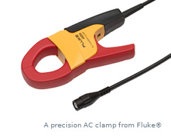
Conventional current probes achieve this by concentrating the field into a gap within a loop of high Mu material. The field is then measured by a field sensor inserted into the gap, often a Hall effect device.
Alternatively ac current can be measured by transformer action whereby the loop of magnetic material creates a one turn primary from the conductor that is enclosed. Hybrid devices typically use a field sensor for dc and low frequencies plus a transformer for higher frequencies.
Normally the probe provides a method of mechanically splitting the magnetic circuit to enable the conductor to be inserted. The position of the conductor within the loop has relatively little effect upon the measurement.
PCB track current measurement
Measuring current in a PCB track presents particular difficulties because it is normally not possible either to break the track or to enclose it within a magnetic circuit. Typically engineers have to guess at the current flowing in a track from voltage measurements made in other parts of the circuit.As electronic design moves towards ever higher densities, development omits the 'bread board' stage and goes straight to PCB design. The inability to observe and measure currents in a circuit under development can pose a serious problem for engineers.
Miniature Fluxgate Magnetometer
The only practical way to observe and measure the current in a PCB track is by sensing the field in very close proximity to the trackTo achieve a calibrated measurement, the field sensor must be capable of maintaining a precise distance from the track. To achieve good sensitivity this distance must be very small because field reduces with the square of distance (to a first order approximation).
 To create a practical current measurement probe, a very special type
of miniaturized sensor was needed. The requirements included very small size with precision
dimensions, dc sensing capability, wide ac bandwidth, and low
noise. None of the existing
sensor technologies used within field and current probes was suitable for this.
Instead the I-prober uses a patented miniaturized version of a
fluxgate magnetometer. Fluxgate magnetometers have been around
for many years but not in miniature form.
To create a practical current measurement probe, a very special type
of miniaturized sensor was needed. The requirements included very small size with precision
dimensions, dc sensing capability, wide ac bandwidth, and low
noise. None of the existing
sensor technologies used within field and current probes was suitable for this.
Instead the I-prober uses a patented miniaturized version of a
fluxgate magnetometer. Fluxgate magnetometers have been around
for many years but not in miniature form.
It is the patented miniaturization that enables it to measure the field at a precise point in space. In addition, the miniature sensor has much lower noise and much wider bandwidth than a conventional fluxgate magnetometer.
Potentially, a similar result could be achieved with other types of field measuring device such as a Hall effect sensor, but no other device offers anywhere near the same combination of low noise, wide dynamic range and wide bandwidth.
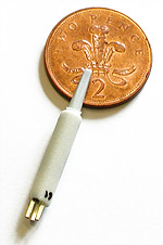
The illustration shows the miniature sensor that is fitted inside the Aim I-prober 520. The field sensing element is located at the very tip of the sensor. The tip of the probe is 2.8mm × 1.8mm including insulation.